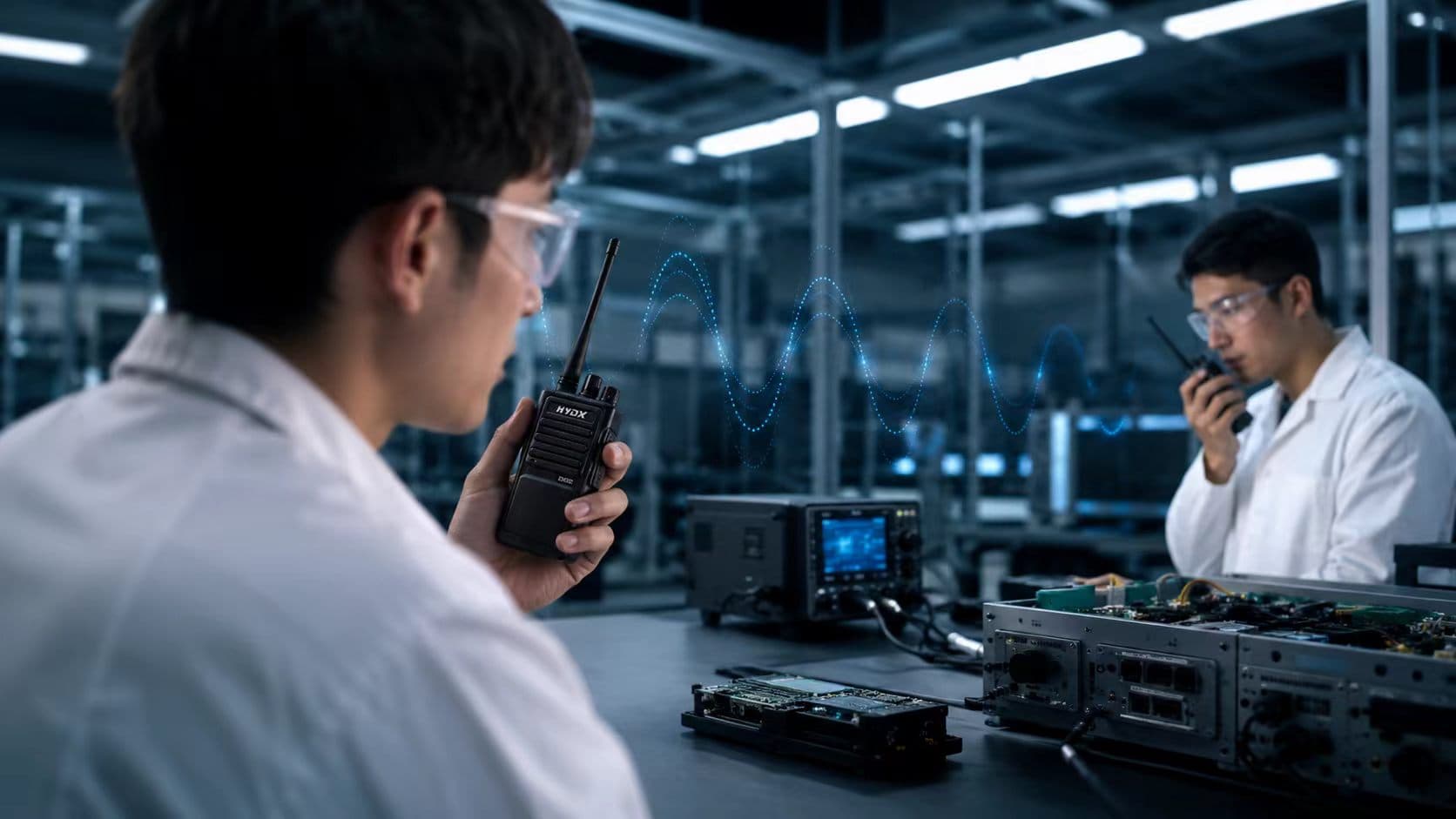
産業、緊急時、屋外のシナリオにおける通信の信頼性、運用上の安全性、および環境耐久性を確保するため、
d
デジタルモバイルラジオ
厳格な一連の工場試験を受けなければなりません。これらの手順は、次のような国家規格に準拠しています。
GB/T 15844-2022
そして
GB/T 32659-2016
輸出モデルについては、国際規格を含む
FCC
そして
CE
すべてのテストに合格したユニットのみが最終出荷となります。以下のセクションでは、業界全体で使用されている主要な性能および信頼性指標を取り入れ、より高度な技術的精度でテスト項目を詳細に説明します。
1. コアRF性能テスト
1.1 送信機テスト
干渉や通信範囲の損失を避けるため、搬送波の平均電力が法定限度内であることを確認します。測定には、正確な平均電力検出機能を備えたピーク電力計を使用します。TDMA方式のデジタル無線機の場合、バースト電力プロファイル(立ち上がり/立ち下がりタイミング、オーバーシュート、過渡特性)が、該当する無線インターフェース規格に準拠していることを確認します。
極端な温度および電圧条件下での搬送波周波数誤差を百万分率 (ppm) で測定します。テストには、搬送波周波数許容誤差と周波数ウォームアップドリフトが含まれます。
GB/T 15844.2
これにより、電源投入時の過渡現象中に無線機が常にオンチャネルを維持し、隣接チャネル干渉を防ぐことができます。
– 隣接チャネル電力(ACP)は、必要に応じてRMS検出器および準ピーク検出器を使用して測定されます。
– 伝導性および放射性のスプリアスエミッションは、ITU-R SM.329および各国のスペクトルマスクに準拠するように評価されます。
チャネル変更時およびPTT遷移時のスペクトル封じ込めを保証するため、一時的な隣接チャネル電力(スイッチング関連のスプラッター)を監視します。
主要な指標としては、クリアなデジタル音声およびデータ伝送のための誤差ベクトル振幅(EVM)とピーク対平均電力比(PAPR)が挙げられます。DMR無線機の場合はシンボル偏差とFSKエラーが評価され、P25の場合は変調忠実度が測定されます。これらのパラメータは、ビット誤り率性能とスペクトル効率に直接相関します。
1.2 受信機テスト
正しい復調に必要な最小入力レベルが測定されます。アナログ機器の場合、12 dB SINAD感度が標準です。デジタル機器の場合、感度は特定のビット誤り率(例えば、5% BER)で定義されることがよくあります。このパラメータは、使用可能な通信範囲を大きく左右します。
隣接チャネル選択性(ACS)と同一チャネル除去機能により、混雑したスペクトル環境下でも受信が保証されます。
・相互変調除去特性とブロッキング特性により、帯域外または近傍に強力な送信機が存在する場合でも安定した動作が保証されます。
受信機のダイナミックレンジは、受信信号強度の広い範囲にわたってオーディオ品質を維持することが検証されています。

2. 電気安全とオーディオ性能
2.1 電源とバッテリーの安全性
過充電、過放電、短絡、過熱保護機能
通常状態と単一故障状態の両方で検証されています。
サイクル寿命と充放電効率が記録されます。
本質安全防爆型モデルの場合、バッテリー試験はATEX/IECEx ia/ibの要件に準拠しており、最大開放電圧、最大内部容量/インダクタンス、および表面温度制限の検証が含まれます。
2.2 電気・EMC試験
絶縁抵抗、耐電圧(耐電圧試験)、接触電流(漏洩電流)、および保護接地接続の連続性は、GB 4943.1-2022 に従って確認されます。
IEC 61000-4-2に基づき、接触放電電圧は±8 kV、気中放電電圧は±15 kVとする。性能基準A(故障なし)またはB(一時的な劣化だが自己回復する)を満たす必要がある。
2.3 オーディオ性能
-
周波数特性、全高調波歪み(THD)、信号対雑音比(SNR)、最大音圧レベル、およびスケルチブロック/リリース特性を測定します。これらのパラメータはすべて、聴覚を保護するために制御された音量レベルで、明瞭でフィードバックのない音声を実現します。
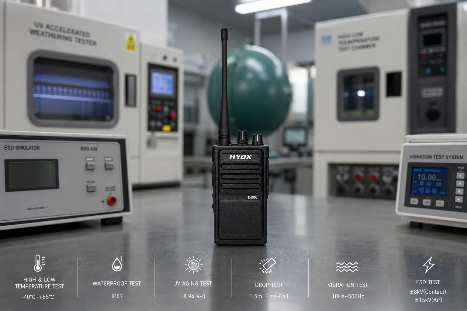
 3.環境適応性試験
-30℃~+60℃での動作試験(最低2時間の浸漬、温度変化率≤3℃/分で熱衝撃を回避)と、-40℃~+85℃での保管試験を実施します。復旧後、すべてのRFパラメータと機能を再検証し、部品の損傷や性能低下がないことを確認します。
– 湿熱:40℃/93%RHで48時間(定常状態)。過酷な使用条件では、周期的な湿熱(例:-10℃~+55℃、95%RH)を適用してもよい。
塩水噴霧試験:5% NaCl溶液中、35℃で48時間(一般産業用)。船舶用および消防用モデルは通常96時間以上を要する。絶縁体の劣化、孔食、構造腐食は一切許容されない。
産業用モデルの場合、最低でもIP67規格に準拠し、完全な防塵性と一時的な水中浸漬(水深1mで30分間)に対する保護性能を備えている必要があります。船舶用/消防用モデルでは、特定の水深と浸漬時間(例:水深2mで2時間)でIPX8規格が求められる場合があります。
運用シナリオで必要とされる場合、低圧試験、太陽放射試験、およびカビ発生試験は、関連する国内および国際規格に従って実施されます。
 4.機械的信頼性試験
– 全モデル共通で、コンクリート面への1.5mの自由落下試験(6面)。
– 転倒試験:IEC 60068-2-31に基づき、直径1mの回転ドラム内で200サイクルの転倒試験を実施。これは、現場での使用中に繰り返し発生する落下をシミュレートするものです。亀裂、部品の緩み、はんだ接合部の破損は許容されません。
– 振動:10~500Hzの正弦波またはランダム振動、各軸につき2時間(3軸)。
– 衝撃:半正弦波パルス、商用向けは30g/6ms、工業用は75g/6ms。
– BGAのはんだ接合部および内部接続部のサンプリングX線検査により、ずれや微小亀裂を検出します。
– PTTスイッチとロータリーコントロール:電気負荷下で10万回以上のサイクルに耐える。接触抵抗を監視し、過度のドリフトを検出します。
– バッテリー/アンテナ/オーディオコネクタ:接触抵抗チェックを含む1,000回以上の挿入/取り外しサイクル。
– タッチスクリーン:機能検証付きで100万回以上のタップ/スワイプが可能。
-耐圧性および耐転位性試験。
・筐体はUL94 V-0の難燃性等級を取得しており、火災の延焼を防ぎます。
 5. 機能適合性、最終検査および高度な検証
すべてのユニットは、PTT応答、スケルチ動作、チャンネル切り替え、暗号化/復号化、GPS/BeiDou測位、Bluetooth接続、アラーム機能、およびアクセサリ検出について検査されます。
RFパラメータとモデル名は、型式承認証明書(国内販売の場合はSRRCまたはCCC、輸出の場合はFCC Part 90/95、CE RED、またはIC)と照合されます。防爆型モデルの場合、本質安全防爆表示、ガスグループ、温度クラス、および電気安全パラメータは、認証文書と完全に照合されます。
国家規格に基づく定期的な型式試験サンプリングでは、包装された製品に対する振動、落下、および気候ストレス(例:ISTA輸送シミュレーション)を試験し、物流条件下での包装の完全性を確保します。
高信頼性が求められる用途(公共安全、軍事など)では、設計検証時に高加速寿命試験(HALT)を適用して、設計マージンを迅速に明らかにすることがよくあります。さらに、高密度電磁環境における性能を完全に特性評価するために、同一チャネル除去比、ダイナミックレンジ、FMハムノイズ(アナログの場合)などの受信機の高度な特性評価指標が用いられることもあります。
この試験プログラムの各段階は、危機的な状況下で途切れることのない通信を実現するという約束を強化するものであり、小型デバイスを緊急対応、産業活動、屋外ミッションにおける信頼できる生命線へと変貌させる。
実際の試験基準は、HYDX研究所および顧客の要求事項に従って実施されます。